
UglyDrone PDU-12S
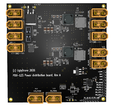
UglyDrone PDU-12S is a smart power distribution unit for UAVs, rovers, and autonomous robotic platforms operating from a 12S / 48V battery bus. It provides protected 12V and 5V power rails, switched high-side outputs for mission payloads, integrated voltage and current monitoring, and intelligent power sequencing.
The unit enables autonomous systems to selectively power companion computers, sensors, communications, and payloads only when required, improving endurance, reliability, and serviceability.
Key Features
Simple to integrate into any platform with direct support for GPIO, UART, and DroneCAN.
Dedicated channel switching control for precise power management of payloads.
Provides a fused high-voltage bus protection layer to prevent catastrophic power failures.
Specially designed for airframes and robots to efficiently disable heavy payloads during transit segments.
Seamless integration with ArduPilot or PX4 firmware as relay/hardpoint entities.
Real-time voltage and current monitoring on all main rails for battery management and load profiling.
Pinout and Dimensions
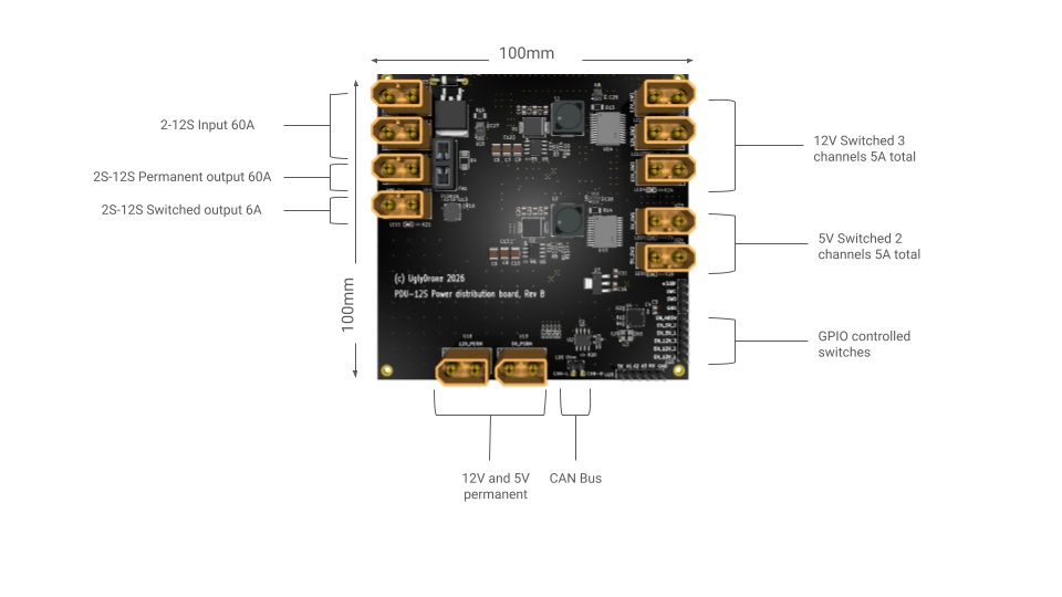
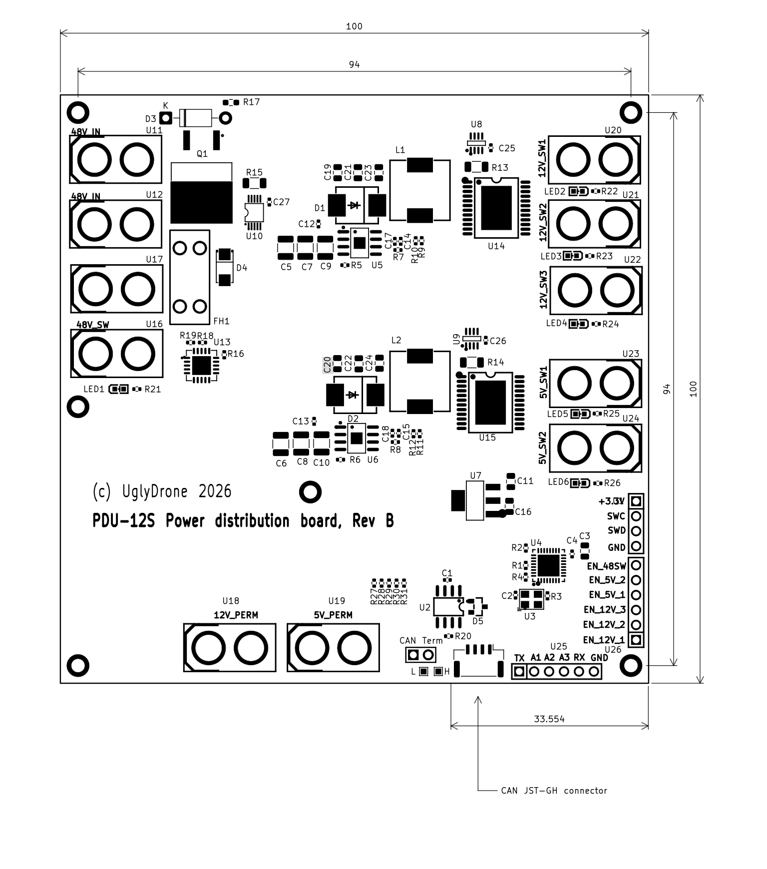
Use the switcher below to view either the board pinout diagram or the physical blueprint dimensions:
Specification
| Model | DroneCAN | 12V Current | 5V Current | 12V Switched Channels | 5V Switched Channels | 48V Switched Channels |
|---|---|---|---|---|---|---|
| PDU-12S | No | 5A | 5A | 3 | 2 | 1 |
| PDU-12S Pro | Yes | 5A | 5A | 3 | 2 | 1 |
Usage Example
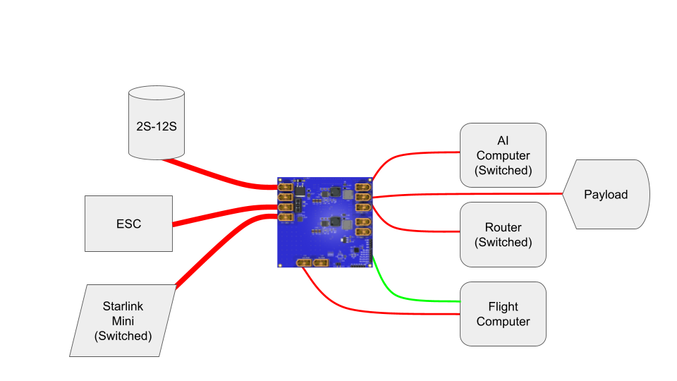
The UglyDrone PDU-12S enables mission-aware power management by integrating with an ArduPilot or PX4 flight controller through configurable GPIO outputs.
During mission planning, GPIO-controlled outputs can be assigned to power groups such as companion computers, AI accelerators, cameras, SATCOM terminals, sensors, or other payloads. At mission start, the PDU powers all required subsystems, allowing sufficient time for system initialization, GNSS acquisition, telemetry establishment, and payload self-tests. Once the vehicle reaches the long-range transit segment, non-essential equipment is automatically powered down, leaving only the flight controller and critical avionics operational to maximize endurance.
At predefined mission waypoints or in response to mission events, the autopilot can selectively restore power to communications or AI payloads for telemetry synchronization, route updates, environmental assessment, or autonomous target recognition before returning them to a low-power state. As the vehicle approaches the operational area, all required mission systems are reactivated, enabling full payload capability and, if required, establishing a low-latency operator link for supervised operation or manual mission completion.
Configuration Console
The PDU exposes an interactive serial port console (115200 baud, 8N1) for advanced configuration, diagnostics, and serial-based control. The console supports command history (up/down arrow keys) and TAB autocompletion.
Available Commands
help- Shows the list of available commands.status [N]- Prints sensor telemetry. If N is specified, it refreshes automatically every N seconds until any key is pressed.outputs- Lists all switched rails, their current state, and default startup states.set [1-6] [0|1]- Sets the state of a channel immediately (e.g.set 1 1turns Channel 1 ON).default [1-6] [0|1]- Configures the default startup state for a rail and saves it to Flash.mode [keep|default]- Configures startup restore behavior:keep: Restore rails to their last active state before power loss.default: Restore rails using the predefined default startup states.
node [1-127]- Changes the PDU's DroneCAN Node ID (Default: 88) and saves it to Flash.dronecan- Displays a live table of discovered active nodes on the bus.dronecan debug- Enters command logging mode to print incoming hardpoint commands.restart- Reboots the PDU.
Console Output Example
PDU> status

--- Sensor Readings ---
  5V Rail (U9 - INA219)   :  5.01 V |     35 mA | 0.17 W  (EN_5V_OUT1, EN_5V_OUT2)
  12V Rail (U8 - INA219)  :  12.00 V |     55 mA | 0.66 W  (EN_12V_OUT1, EN_12V_OUT2, EN_12V_OUT3)
  48V Rail (U10 - INA228) :  48.22 V |    119 mA | 1.45 W  (EN_48VSW)

PDU>
DroneCAN Integration
The PDU operates on a DroneCAN bus accepting hardpoint commands to trigger outputs. Once connected to a Flight Controller, check that the UglyDrone PDU is present on the bus using the DroneCAN GUI tool:
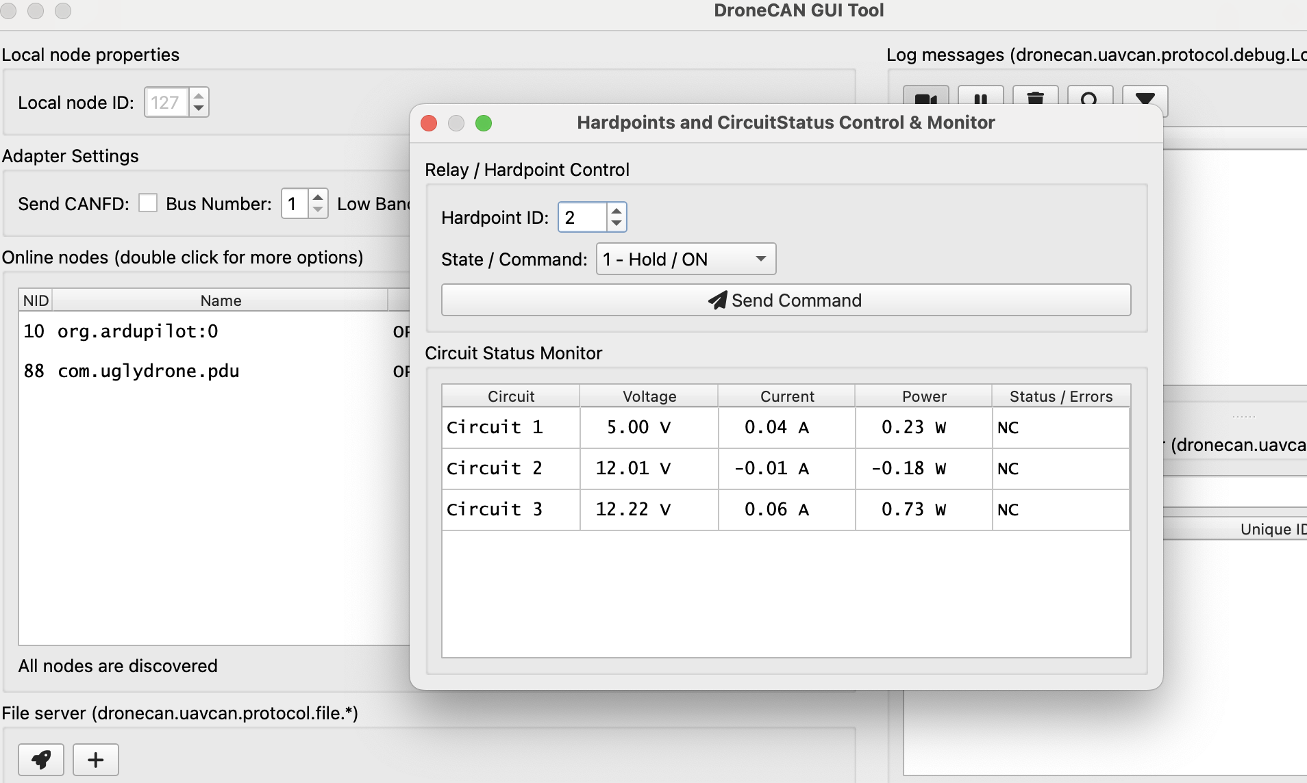
Once visible on the bus, configure the Ardupilot relays as hardpoints:
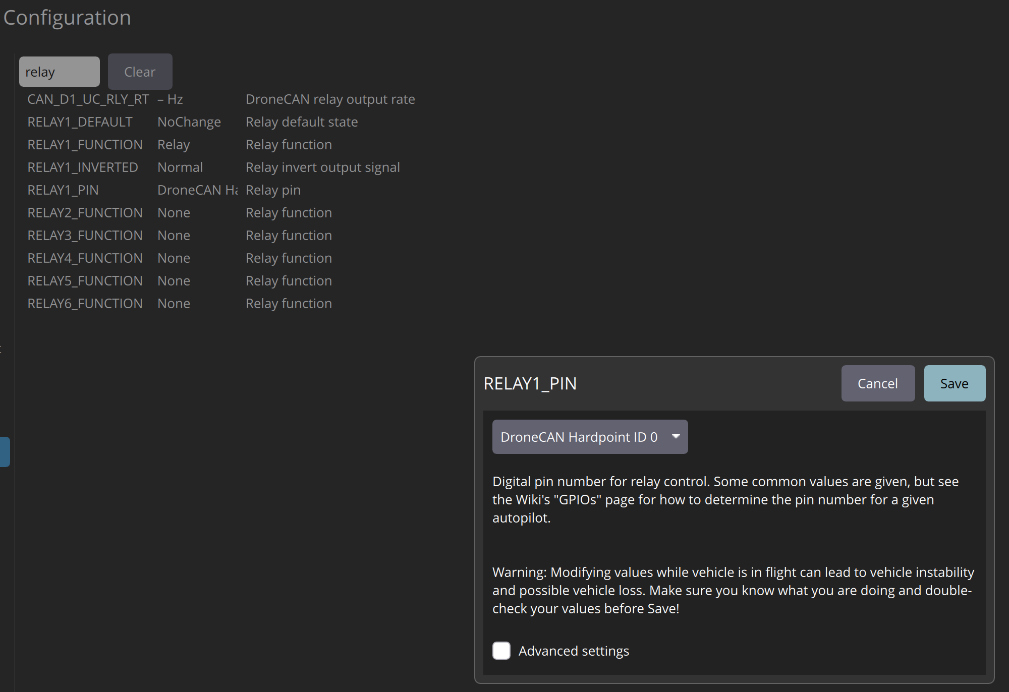
Mapping of PDU Outputs to Hardpoints
| PDU Switched Output | Hardpoint Index |
|---|---|
| 48V SW | Hardpoint 0 |
| 12V SW1 | Hardpoint 1 |
| 12V SW2 | Hardpoint 2 |
| 12V SW3 | Hardpoint 3 |
| 5V SW1 | Hardpoint 4 |
| 5V SW2 | Hardpoint 5 |
After relays are defined, they can be used during mission planning or mapped to RC transmitter channels.
Note: The PDU also transmits real-time telemetry using standard uavcan.equipment.power.CircuitStatus DroneCAN messages. Check your flight controller software manual for compatibility.